1. Upload & Setup
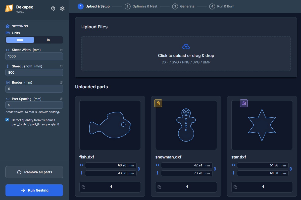
As the first step, you need to upload your design files, set up part quantities and sheet parameters. You can also attach raster images to your parts for engraving. Vector engraving is supported as well - just define ENGRAVE layer in your DXF or SVG files.
- 3. Generate – If you want to process only a single file (SVG, DXF or bitmap)
- 4. Run & Burn – If you already have a G-code which you want to execute.
Step-by-step guide
- Configure sheet size – Enter your material sheet dimensions (width × length in mm).
Set part spacing – Spacing is the minimum gap between parts. Small values < 3 mm may slow down the nesting, because the algorithm needs to place parts with high precision.
Set border – Border is the minimum gap between parts and sheet edges.
You can also enable/disable automatic part quantity detection from filenames (applied during file upload).
- Upload design files – Click the upload area or drag and drop your files on the upload area. You can upload DXF, SVG or bitmap files.
- Set part parameters – Enter how many copies of each part you need. Check preview of the part and adjust dimensions if needed. You can click the part for enlarged view.
Apply grain lock if needed. Locked part will not be rotated during nesting.
Attach raster engrave if you want to engrave an image on the part.
- Run nesting – Click Run nesting to start.
For best results, see guides How to Prepare DXF Files and How to Prepare Bitmap Files.
Attach Raster Engrave
You can attach a raster image (PNG, JPG, BMP) to any uploaded vector part. This image will be engraved on the part surface during the cutting process.
To open the raster engrave settings, click the button on a specific part. The button is visible when you hover over the part.
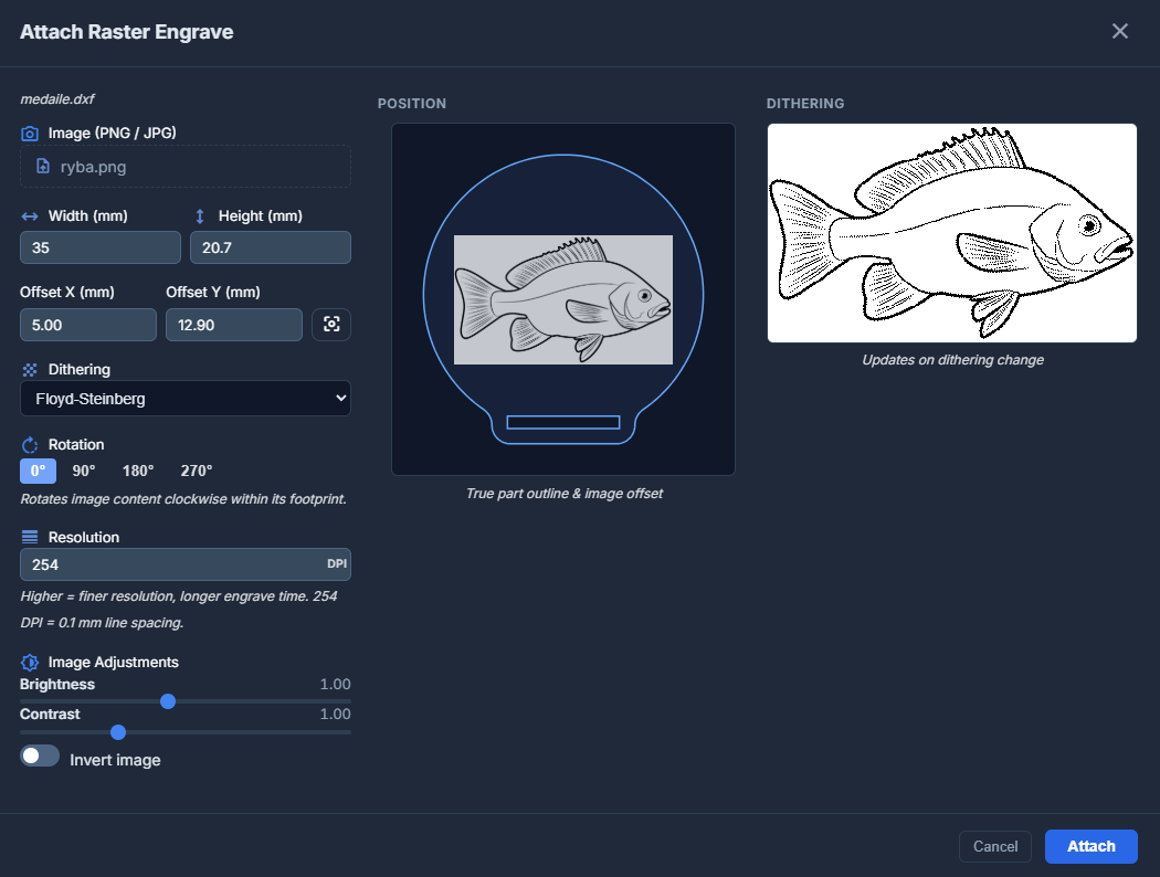
Settings available in the modal:
- Width & Height – Scale the image to specific dimensions in millimeters.
- Offset X & Y – Position the image relative to the part's origin. You can use the Center button to automatically center the image on the part.
- Dithering – Choose how to convert the image to dots for engraving:
- Floyd-Steinberg – High-quality diffusion dithering for smooth gradients.
- Bayer (ordered) – Geometric pattern dithering.
- None (threshold) – Hard black and white based on a threshold value.
- Rotation – Rotate the image content (0°, 90°, 180°, or 270°).
- Resolution (DPI) – Adjust the level of detail. 254 DPI corresponds to 0.1 mm line spacing. Higher values result in better quality but longer engraving times.
- Image Adjustments – Fine-tune brightness and contrast. You can also Invert the image (useful for engraving objects on dark materials).
The modal provides a real-time Position Preview showing the true part outline and image offset, along with a Dithering Preview to see how the image will actually be processed.