1. Upload & Setup
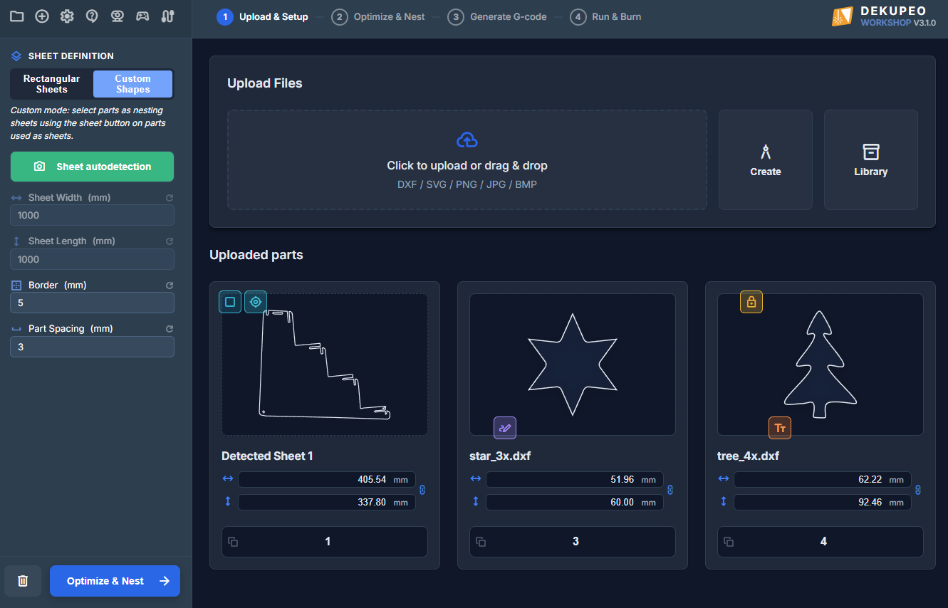
Dekupeo mimics real-life production scenario - you have a sheet of material and a set of parts to cut or engrave. The first step is to upload your design files, set up part quantities, and configure sheet parameters.
Step-by-step guide
- Configure sheet size – Choose between Rectangular Sheets (enter width × length) or Custom Shapes (use uploaded or auto-detected parts as sheet boundaries).
Set part spacing – Spacing is the minimum gap between parts. Small values < 3 mm may slow down the nesting, because the algorithm needs to place parts with high precision.
Set border – Border is the minimum gap between parts and sheet edges.
- Upload design files – Click the upload area or drag and drop your files on the upload area. You can upload DXF, SVG or bitmap files.
- Add from Library – Instead of uploading fresh files, you can quickly add parts from your predefined Product Library. Click the inventory_2 Library button to browse and select parts from your configured library sources.
- Set part parameters – Enter how many copies of each part you need. Check preview of the part and adjust dimensions if needed. You can click the part for enlarged view.
Apply grain lock (lock) if needed. Locked part will not be rotated during nesting.
Rotate (rotate_right) or Mirror (flip) part to match desired orientation.
Attach text engrave (text_fields) if you want to add text or serial numbers to the part.
Attach raster engrave (texture) if you want to engrave an image on the part.
Attach vector engrave (stylus_note) if you want to engrave a vector design on the part.
Split file (splitscreen) Files containing multiple parts must be split before engrave is attached to them.
Duplicate part (content_copy) if you want to create multiple copies of a part with different sizes or engraving.
- Run nesting – Click Run nesting to start.
For best results, see guides How to Prepare DXF Files and How to Prepare Bitmap Files.
Custom Sheet Shapes
By default, nesting uses a rectangular sheet size. If your material has an irregular outline (offcut/remnant), you can switch to Custom Sheet Mode and use a vector contour as the nesting boundary.
- Enable Custom Sheet Mode on the Upload & Setup page.
- Mark one uploaded shape as Sheet (crop_square) .
- Run nesting to place parts inside the custom boundary instead of a rectangle.
Note: Custom Sheet modes are available in Hobby and higher tiers.
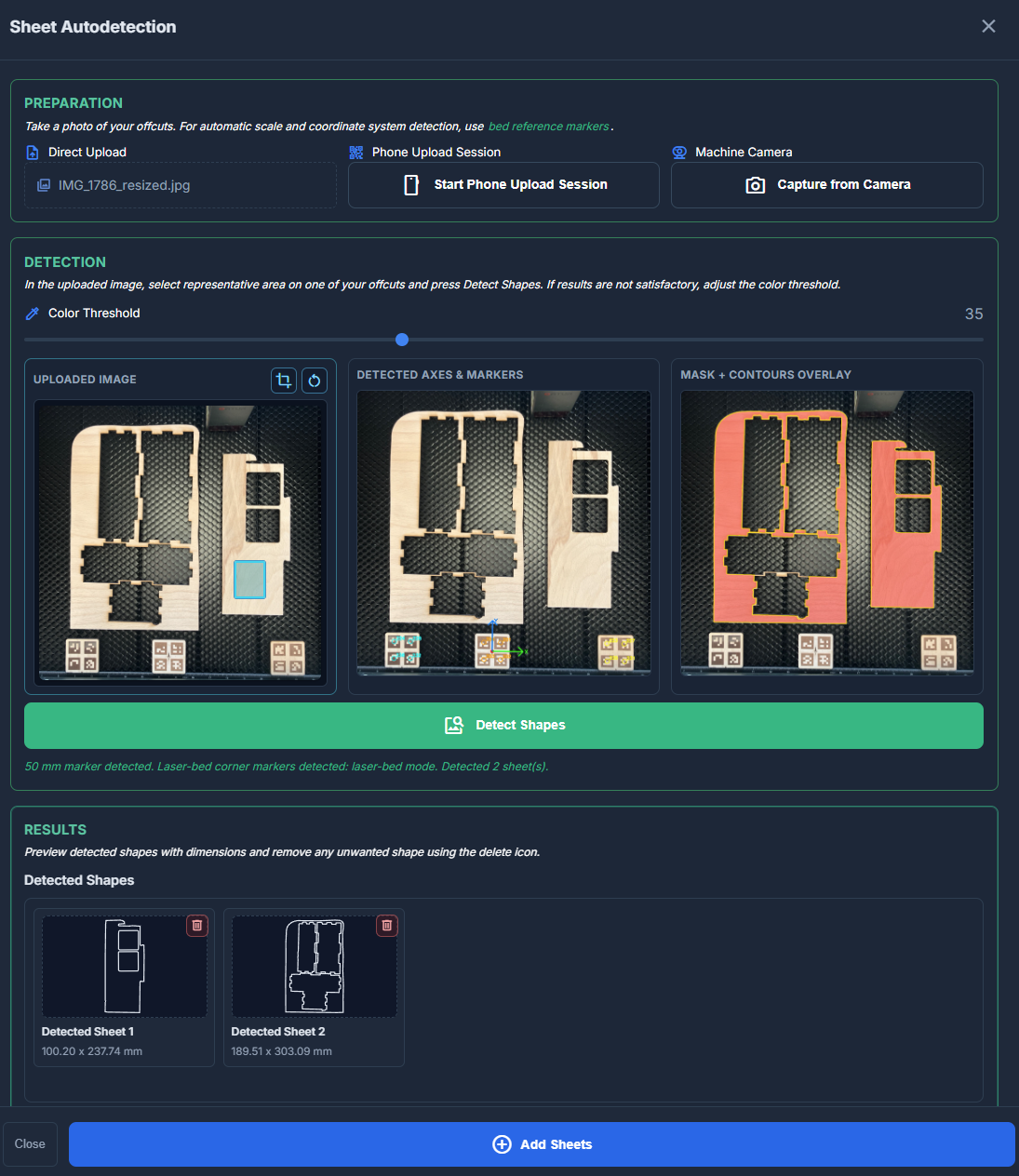
Sheet Autodetection
Sheet Autodetection helps you convert a photo of offcuts (remnants) into a vector boundary for custom-sheet nesting.
- Click on the Sheet Autodetection button.
- Load a sheet photo from your computer, connected camera or phone upload session.
Use contrast background for reliable detection and markers for automatic scale, origin and machine axes recognition. If needed, you can crop (crop) the image to focus on the relevant area. - With mouse drag, select representative rectangle on the off-cut.
- Click Detect Shapes button. The processing may take a few moments.
- Review generated contour previews, retry with better image or adjusted threshold if needed.
- Add as Sheet to insert the detected boundary into the parts list and use it as the custom nesting sheet.
Sheets detected with at least two corner markers are bound to the machine coordinate system and marked with my_location icon.
Learn how to use markers for accurate scale, origin, and machine axes recognition.
Note: Shape Autodetection is available in Workshop and higher tiers.
Add From Library
The Product Library allows you to store frequently used parts and quickly add them to your nesting project without re-uploading the original design files.
- Click the inventory_2 Library button in the Upload Files section.
- Select the Source (folder) you want to browse. Sources are configured in the Settings > Library page.
- Use the Filter input to search for parts by name or subfolder path.
- Select the parts you want to add and click Add Selected.
CSV Import: You can also import a CSV or TXT file to quickly set quantities for library parts. The file should contain rows in format: part_filename;quantity.
For more details, see tutorial: Using the Product Library.
Attach Text Engrave
You can add text markings directly to any uploaded part. This is useful for part identification, branding, or creating personalized items.
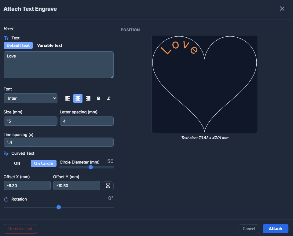
To open the text engrave settings, click the button on a part. The modal offers two modes:
Text Modes:
- Default text – The same text is engraved on all copies of the part.
- Variable text – Allows you to specify different text for each copy of the part (e.g., for serial numbers, name tags, or price labels). You can manually enter values and quantities or Import CSV with the list of values.
Appearance Settings:
- Font – Select from several available fonts (e.g., Mono for technical markings, Script for decoration).
- Styling – Adjust alignment (Left/Center/Right) and style (Bold/Italic).
- Size & Spacing – Set the text height and adjust letter/line spacing.
- Positioning – Drag the text to the desired area with the mouse, set X/Y offset relative to the part origin, or use the Center button.
- Rotation – Rotate the text block.
- Curved – Apply a curved effect to the text.
The preview on the right shows the exact position and scale of the text on your part. Text is automatically oriented if the part is rotated during nesting.
Attach Raster Engrave
You can attach a raster image (PNG, JPG, BMP) to any uploaded part.
To open the raster engrave settings, click the button on a part. The button is visible when you hover over the part.
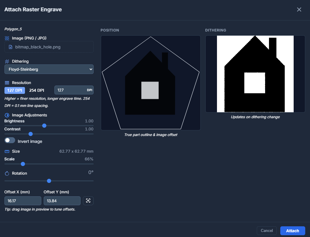
Settings available in the modal:
- Dithering – Choose how to convert the image to dots for engraving:
- Floyd-Steinberg – High-quality diffusion dithering for smooth gradients.
- Bayer (ordered) – Geometric pattern dithering.
- None (threshold) – Hard black and white based on a threshold value.
- Resolution (DPI) – Adjust the level of detail. 254 DPI corresponds to 0.1 mm line spacing. Higher values result in better quality but longer engraving times.
- Image Adjustments – Fine-tune brightness and contrast. You can also Invert the image (useful for engraving objects on dark materials).
- Scale – Scale the image to the desired size.
- Rotation – Rotate the image content (0°, 90°, 180°, or 270°).
- Offset X & Y – Drag the image to the desired area with the mouse, set X/Y offset relative to the part origin, or use the Center button.
The modal provides a real-time Position Preview showing the true part outline and image offset, along with a Dithering Preview to see how the image will actually be processed.
Attach Vector Engrave
In addition to raster images, you can also attach files to be engraved onto your parts in vector mode. This is ideal for logos, text, or technical markings that require sharp vector lines.
You can attach vector files in SVG or DXF format or bitmap images which will be converted to vector paths automatically.
To open the vector engrave settings, click the button on a part. The button is visible when you hover over the part.
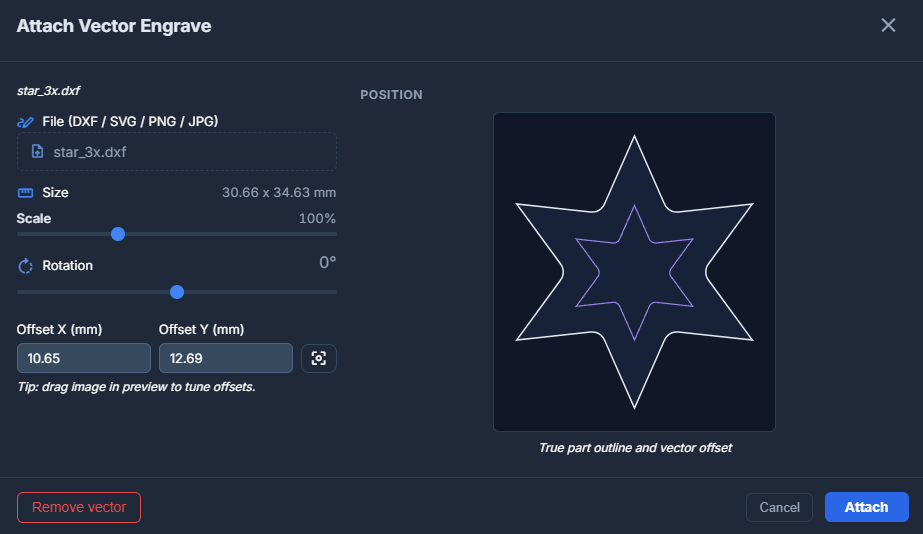
Settings available in the modal:
- Scale – Scale the vector design to the desired size.
- Rotation – Rotate the vector engrave.
- Offset X & Y – Drag the vector engrave to the desired area with the mouse, set X/Y offset relative to the part origin, or use the Center button.
Similar to raster engraving, vector engrave paths are automatically moved and rotated together with the part during the nesting process.
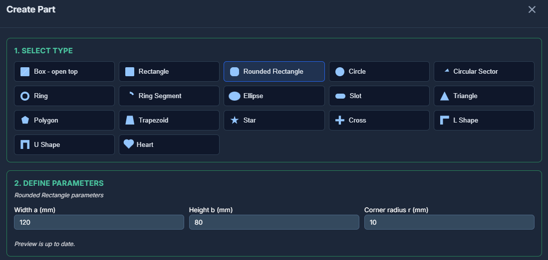
Create Part
Dekupeo is not a vector design tool, nevertheless it allows you to create some basic parts based on predefined shapes and dimensions. To do so, click the button architecture Create, select part type and set the desired dimensions.
Generated parts can be directly used in your project or saved as SVG file for later use.
Continue to Optimize & Nest to learn more about true-shape nesting for laser cutting.