Introduction
Dekupeo is a desktop application for laser cutting and engraving. It helps you go from part files (DXF, SVG, bitmap) to optimized nests, generated G-code, and machine execution in one place.
Dekupeo is not a graphical editor, but rather a tool focused on effective production of designs prepared elsewhere (e.g., in CAD or vector graphics software).
Dekupeo is available as a desktop app for Windows and Linux. For Linux-specific installation and run details, see Run on Linux.
Basic App Layout
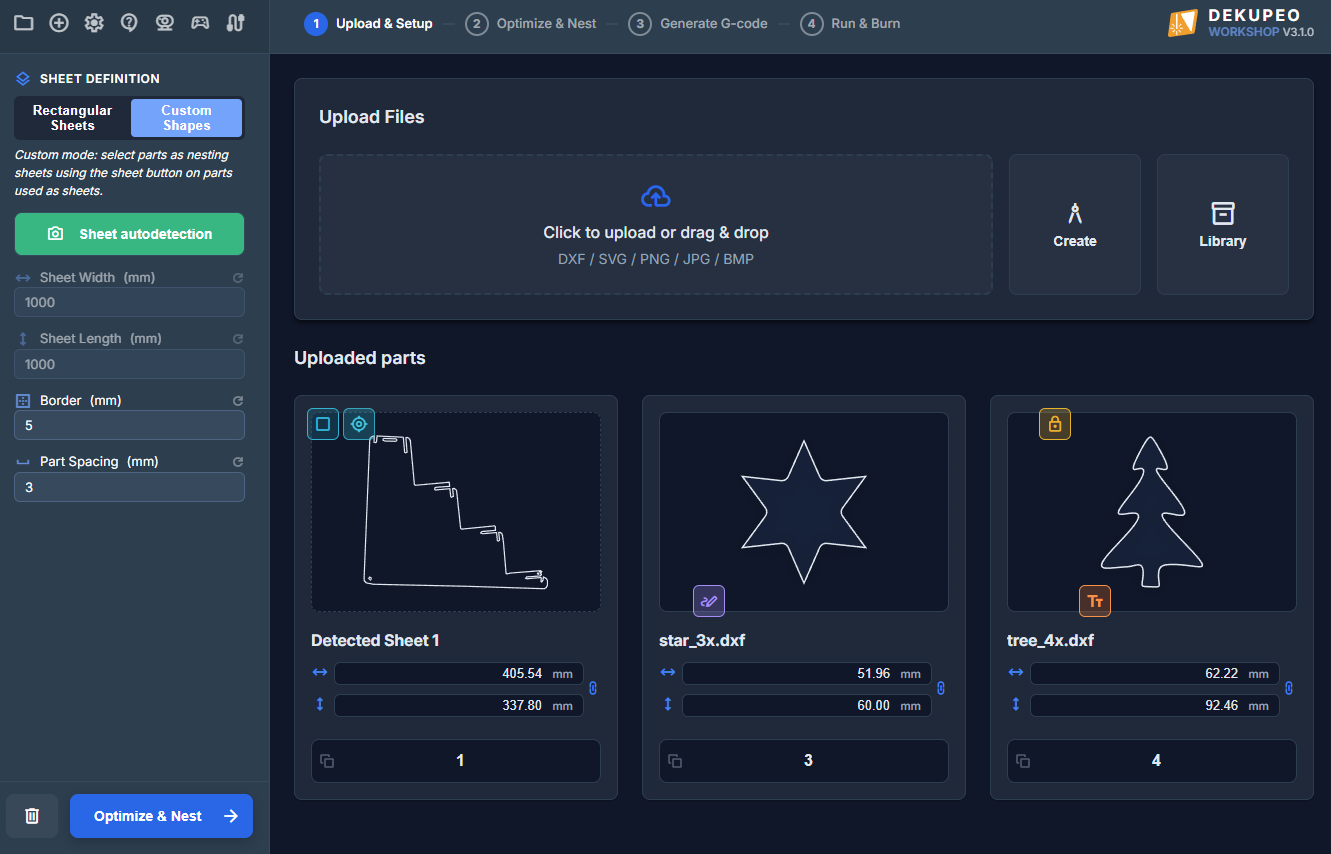
The interface is organized into four primary areas:
- Application Menu - located at the top left, providing quick access to global app actions (Project, Create, Settings, Support, camera/gamepad status, and machine connection).
- Left Sidebar - serves for parameter settings for active workflow step. At the bottom of the sidebar, there are buttons for navigation between workflow steps.
- Top Workflow Bar - serves as navigation for the production flow: Upload & Setup -> Optimize & Nest -> Generate G-code -> Run & Burn.
- Main Work Area - the active page where you import files and see the results of each step.
Application menu
Application menu consists of several icons:
- Project menu - open the project actions menu.
- Create menu - open quick creation actions (new cut/engrave/test tasks).
- Settings - open app settings (machines, materials, camera, controls).
- Help & Support - opens support resources.
- Camera overview - opens the camera monitoring window.
- Gamepad status - indicator and shortcut to gamepad settings.
- Connection status - opens machine connection controls.
Project Menu
The Project menu handles project file lifecycle:
- New project - start a blank project.
- Open project - load an existing
.dkpproject file. - Save project - save current project changes.
- Save project as... - save a copy under a new name/location.
The bottom section also shows Recent projects for fast reopening.
Create Menu
The Create menu is used to start simple actions which do not use nesting:
- Cut Single Part - import one part for cutting.
- Engrave Raster - prepare a bitmap image engraving operation.
- Engrave Vector - prepare vector engraving paths.
- Engrave Text - create text engraving.
- Auto Engrave - automatic object positioning/orientation engraving workflow (available from Workshop licence).
- Generate Test - create test patterns for speed/power calibration.
- Upload existing G-code - load already generated G-code for execution.
Need Help?
If you need help with setup, licensing, or troubleshooting, contact support at support@dekupeo.com.
Continue to Upload & Setup to learn more about file upload and sheet setup for laser cutting.